CHAPTER 2 – ADVANCED PROGRAMMING
Now we get into the real "magic" of the Event Processor. This section shows how several of the basic features of the device can be used together to solve very complicated MIDI snags. It also discusses several options seen on the features discussed in earlier sections, which were deliberately left out of the Basic Programming discussions.
VARIABLES
The Event Processor has two Variable locations to save off MIDI data, while the Event Processor Plus has eight of these locations. We’ve intentionally left out this ‘basic’ tool, the setting of Variables, in our earlier discussions. We did this because while setting a variable is an easy task, the variable has no purpose until we use it to affect the way the Event Processor looks at data.
Sometimes, in order to solve a problem with MIDI gear, we need to know something about the data that was already sent. MIDI doesn’t provide any way to look at past data; it’s strictly a real-time communications link. A MIDI device could, of course, store up a record of past MIDI communications, but this takes hardware and software resources and few if any devices bother to record MIDI for later use. Of the few devices that do, almost none of them allow the user to access the data. Fortunately, the Event Processor can remember previous data for later use.
Let’s say that we have a synthesizer that reinitializes a bunch of settings –- volume, filter, Mod Wheel position, etc. –- every time we change programs. That’s a useful in some applications (like sequencer recording), but when playing live, it’s very strange to hear the reverb knob jump from zero to a large value when touched after a Program Change. Yes, we can try to remember to always wiggle the reverb knob after a Program Change, but we’ll probably forget sometimes. The Event Processor can make things much better! We can save off the setting of the reverb knob, Mod Wheel, and other settings every time they move, and then reapply the latest settings after each Program Change. We’ve effectively changed the way the synthesizer handles Program Changes, without having to touch the synthesizer. Figures 12 and 13 show how this can be done, using the Mod Wheel for our example.
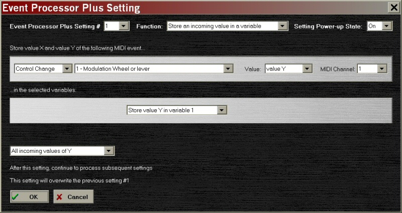
Figure 12 -– Saving the Mod Wheel Position as a Variable
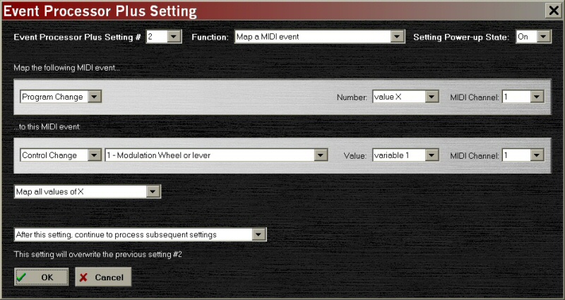
Figure 13 -– Sending a Previous Mod Wheel Value
Remember that mapping the Program Change to the Mod Wheel setting automatically takes the Program Change out of the MIDI data. Although we haven’t shown it here, we probably also want to map the Program Change to itself with a third Setting.
Another use for Variables is selective filtering of new MIDI events. Let’s say that we can’t eliminate all of the "hiccups" when a Program Change happens, the way we removed the Mod Wheel problem. Perhaps some of them are necessary changes to make our live show work. The changes are still bothersome, though, because they prevent playing the keyboard for a couple of seconds while all of the changes are processed. We really wish they wouldn’t happen; at least not all the time. The changes are necessary, but maybe we can reduce the number of times that they happen. If we change the synthesizer to a classic Keith Emerson Moog patch, and our sequencer comes along and calls up the same patch change, why go through the whole mess twice? We’re already set up correctly, right?
Figures 14 and 15 show the settings necessary to remove duplicate Program Change events. Once we receive a certain Program Change, all future Program Change events of the same value will be removed, but Program Changes with a different value will pass through normally.
This example demonstrates that the order of the Settings in a multi-Setting process is very important. If we were to reverse the order of the Settings, Setting #3 would store the Program Change in the Variable first, then Setting #4 would filter the Program Change based on this Variable, and the filtering would happen on every pass, including the first time a Program Change is made. Since we want the first Program Change to pass through, we must store the data in the variable after the filter Setting.
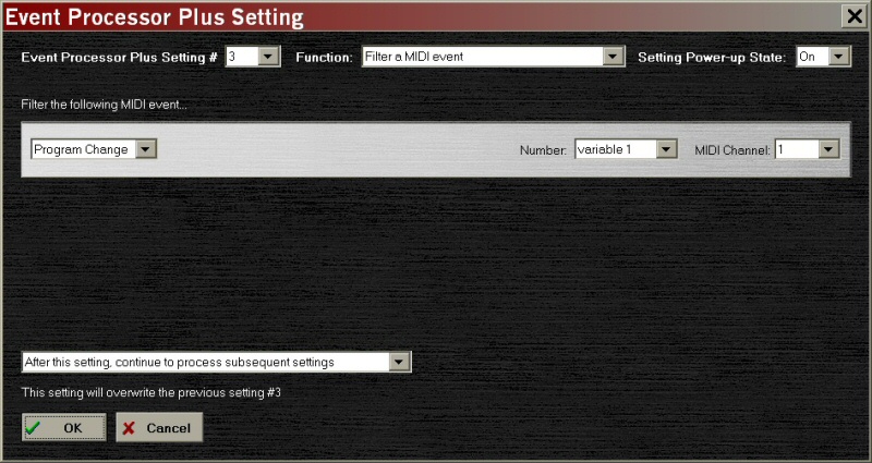
Figure 14 -– Selective Filtering Based on a Variable
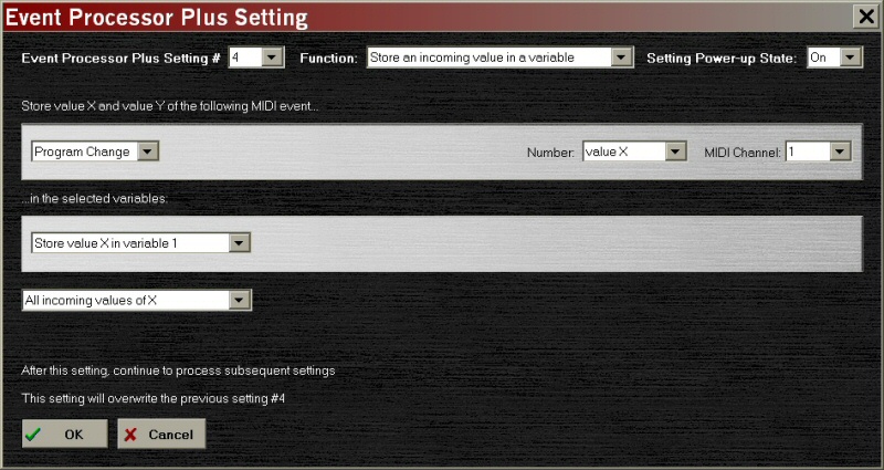
Figure 15 -– Saving the Program Change Number
ADDING FEATURES BY ENABLING AND DISABLING SETTINGS – PART II
No matter how complex and well thought out a MIDI keyboard is, it seems like there’s always at least one feature that the designers left out, right? And on the other side of the coin, there always seems to be at least one knob or button that has no purpose in your playing style. Maybe it’s the volume knob, because you always like to run on "11," or the split button, because you never use splits. If that "useless" control sends out a MIDI message when it’s used, the Event Processor can probably convert the message to something else!
Let’s look at a MIDI master keyboard that has two zones. We’re going to call up a rack of sound modules, however and wherever we want, on Channel 1 and 2. But, we also play left-hand bass once in a while –- not often enough to dedicate one of these zones to bass, but we need this function at times. The bass is on Channel 9, and sometimes it’s used with different combinations of other keyboards, so we want our new "Bass Button" to work with any combination of zones that are in place.
It just so happens that our MIDI master keyboard has a dedicated Celeste On/Off button –- OK, a little weird, but Celeste seemed important back in 1988! We can set things up so that the bottom two octaves of the keyboard do what they normally do when "Celeste" is off, but call in the left-hand bass when it’s turned on. Figures 16 and 17 show how this is accomplished: We create one Setting to re-map Channel 1 and 2 (and any other channel) to Channel 9, and another Setting to enable or disable the first Setting, based on the Celeste Button.
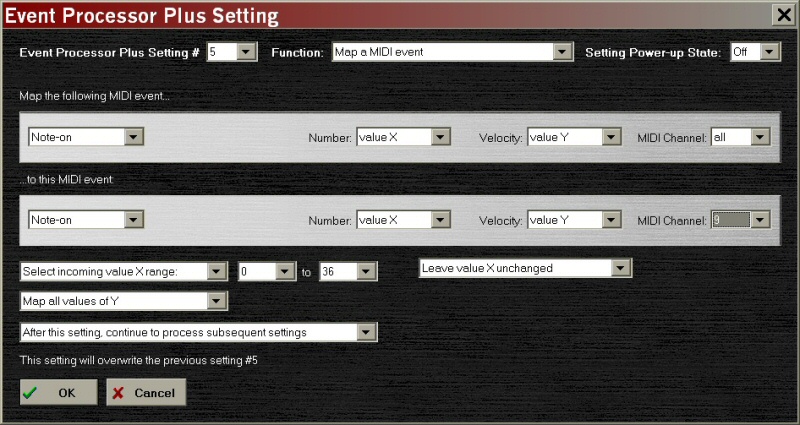
Figure 16 -– Re-mapping the Bass Notes to Channel 9
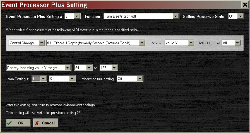
Figure 17 -– Enabling Setting #5 through the Celeste Button
The reader should note that all Settings can be programmed to start enabled or disabled, to work better with other gear. In this case, the Celeste Button starts up disabled, so choosing to disable Setting 1 at startup eliminates the need to hit the Celeste Button a couple of times at the start of the show to synchronize the Event Processor with the button.
As in our earlier Mod Wheel example, there is a problem if we hold down the note while changing the channel: the Note On and Note Off messages will be on different channels. The solution to this problem is to again send All Notes Off messages each time the Celeste Button is pressed.
Similar control could, of course, be accomplished through Program Change 64, the Mod Wheel, a SysEx string, or even hitting the lowest note on the keyboard!
THE ‘ALL’ PARAMETER
In the preceding example, we used a dummy channel called ‘All’ to map the Note On messages to Channel 9, regardless of their origin. This only eliminates one Setting in our simple example, but if the keyboard had four or five zones, the savings would really add up. It’s handy for global filtering Settings, too, such as eliminating Channel Pressure (Aftertouch) on all channels. Without an All variable, eliminating Aftertouch could require as many as 16 Settings, instead of just one.
REVERSE FILTERING
The All variable is also useful for "reverse filtering" or "programming by addition," where we start with a Setting that filters all the data, and then add Settings to let certain events back through to the output. Let’s say that we want to use an old piano module from the ‘80s in our setup. The tone is killer, but the module overloads so easily that we can’t connect it in line with our modern sequencer gear. Aftertouch sends it off, MIDI Clock sends it off –- just about everything an acoustic piano can’t do sends it off. Before we retire it, though, let’s let the Event Processor take a crack at the problems. Figures 18-20 show how just three Settings can limit the MIDI data to the two elements the piano module likes to see: notes and the Sustain Pedal. Everything else is filtered out, regardless of the channel it arrives on.
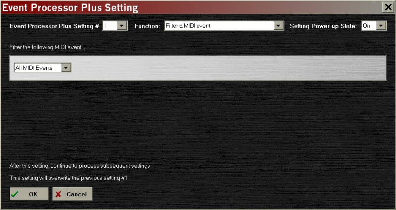
Figure 18 -– Filtering Everything
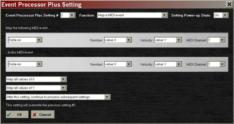
Figure 19 -– Pass the Notes
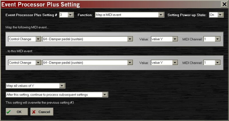
Figure 20 -– Pass the Sustain Pedal
SELECTING RANGES AND SCALING VALUES
Sometimes, it’s not necessary (or even desirable) to send the full range of 128 values that a controller can provide. The Event Processor can be programmed to only send a limited range of values from each Setting, and to scale a range of values from one data type to another. Beyond simple Mapping and Filtering, the Event Processor can selectively process MIDI data. For our next example, let’s consider the control of ‘drawbars’ -– those funny-looking slider-like controls -– on a tonewheel organ. Most manufacturers dedicate nine CC locations, one per drawbar, for controlling this feature. Most manufacturers did so, but not all of them. One of the major organ makers figured that since a real drawbar is actually a nine-position switch, the 0-127 range of nine CCs is wasted in this situation. So, they mapped all nine drawbars to one CC –- 9 drawbars x 9 positions equals 81 values, right? –- saving eight CC locations. It’s a neat trick, except that none of the other manufacturers followed suit, rendering this particular brand of organ pretty much incompatible with the rest of the industry.
Fortunately, the Event Processor can selectively convert the data into the ‘standard’ format so that we can use a different brand of master keyboard as a second manual for the organ, complete with its own set of drawbars. Figures 21 and 22 show two of nine Settings used to convert nine separate CC locations into the mapped single CC that the organ likes to see. Each Setting converts its 0-127 range into a very specific, limited portion of the ‘Master CC’.

Figure 21 -– 16' Drawbar Scaling

Figure 22 -– 5-1/3' Drawbar Scaling
The scaling does not have to be a reduction, as in our example. A small range of MIDI values can be expanded into a larger one, too. Even a reverse mapping -– i.e., making the knob or pedal work ‘backwards’ -- can be programmed. This might be useful in our example if the controller keyboard sends standard slider messages where an ‘up’ push results in a larger control value; simply scale the output from 8 to 0, etc. Just remember that the Event Processor cannot magically add in missing values that never existed in the original data: If a 4-position switch is mapped to the volume pedal, the output values will be 0, 42, 84, and 127, and changing the switch positions will result in audible jumps in the volume.
INCREASING THE CAPABILITIES OF YOUR GEAR
As a general rule, the Event Processor’s capability to add features to your setup is limited only by the imagination –- although sometimes, we have to get "creative" to reach the right result. I have a very nice MIDI master keyboard, whose manufacturer and trade name shall remain nameless, that does just about anything that I could imagine –- well, almost anything. The designers allowed each programmable button to send two different values when used for MIDI CC messages; I’m not limited to just 0 and 127. For whatever reason, though, it only works with CC data. I can’t toggle between two different Program Changes, which would be really useful to save off a collection of often-used stored patches in my gear. (I know, how many Program buttons can a guy need? Well, it’s a master keyboard, and it controls several modules, so the answer is, "more than I have.") How did I get around this?
MIDI defines 128 controllers for CC operations, and most of them are effectively undefined. In fact, the CCs above 100 are practically unused. I dedicated a bank of buttons to call up programs, but rather than send Program Change messages, I programmed each button to send out two different CC#118 values. (All things being equal, CC#118 is pretty harmless.) Then I use the Event Processor to convert CC#118 into Program Change messages, based on the data value of the CC#118, and I’ve tricked the master keyboard into sending two different –- and completely selectable –- Program Changes with each button! Figure 23 shows the details.
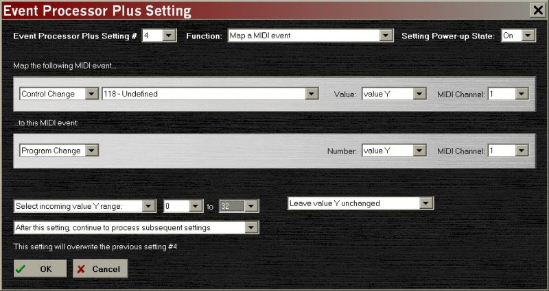
Figure 23 -– Converting CC#118 into Program Changes
Please note that while I could have mapped the entire 128 Program Changes in this Setting, I am only dedicating the first 33 Program Changes to the module on Channel 1. This is because I might want to create a similar Setting for another device on a different channel. Thus, I can split up my Program Change ‘method’ and dole out patches to several devices, all based on the Program Change number –- by using additional Settings, of course. If each of the devices can only accept say, 16 programs, I can ‘recycle’ the Program Change numbers by scaling CC118 values of 0-15 to PG#0 – PG#15 on Channel 1 in this Setting; CC118 values of 16-31 into PG#0 – PG#15 on Channel 2 in another Setting; etc.
CC#118 of value 0 on CH1 --> PG#0 on CH1 CC#118 of value 16 on CH1 --> PG#0 on CH2 CC#118 of value 1 on CH1 --> PG#1 on CH1 CC#118 of value 17 on CH1 --> PG#1 on CH2 CC#118 of value 2 on CH1 --> PG#2 on CH1 CC#118 of value 18 on CH1 --> PG#2 on CH2 ... ... CC#118 of value 15 on CH1 --> PG#15 on CH1 CC#118 of value 31 on CH1 --> PG#15 on CH2
THE SUPER-FOOT-CONTROLLER
One of the more common examples of a rugged, easy-to-use MIDI control for the stage is the "foot controller" option that guitarists add to multi-effects units, especially the rack-mounted type. These controllers usually provide an expression pedal, plus a set of foot switches to call up user programs. (They sometimes have foot switches for CC use, too, which we’ll ignore.) The expression pedal takes care of itself; if not, we can easily change the destination with another event. The program switches, however, aren’t that useful to a keyboard player as-is. First, keyboards usually have other means of calling up programs; and the foot pedals are under the keyboards, and much harder to see. Second, I’ve always felt that the bank-and-four-switches method was a painful way to scroll through 40 or 50 programs on stage, because it’s easy to lose track of which bank is "on deck." Unfortunately, the switches usually can’t be programmed from their factory settings.
Adding an Event Processor to the foot controller can remove this restriction. We can re-map the foot switches to send CC, NRPN, SysEx –- and yes, even Program Change –- messages. For simplicity, let’s use a foot controller that has one Bank switch and four Program switches, with eight banks total. We only want to define two banks of settings for our own use. The first bank will be (surprise!) Program Change messages, while the second bank will send CC commands to turn on reverb and echo effects. The mapping scheme of foot controllers is straightforward: the foot switches send a short series of program messages, while the Bank switch adds an offset to continue to call up more series of PG settings:
Bank = 0 PG#0 PG#1 PG#2 PG#3 Bank = 1 PG#4 PG#5 PG#6 PG#7 Bank = 2 PG#8 PG#9 PG#10 PG#11 ... Bank = 7 PG#28 PG#29 PG#30 PG#31
Since we only want two banks, but our controller sends eight, Banks 2, 4, and 6 will simply mirror the information sent in Bank 0; and Banks 3, 5, and 7 will mirror the information in Bank 1. This means that we can never be more than one bank away from where we want to be, even if we lose track of the bank number. Figure 24 shows the first of the three ‘mirror’ events, where we take PG#8-PG#11 and re-map them to PG#0-PG#3. We need only three of these events, because it’s not necessary to re-map Bank 0; it already does what we want.
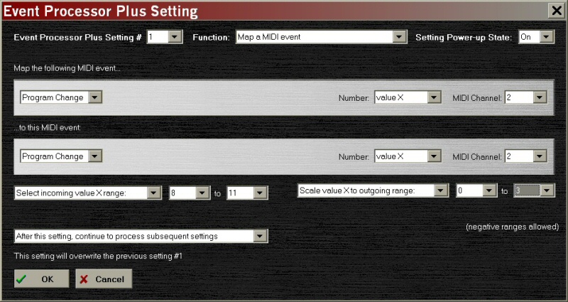
Figure 24 -– Mirroring PG Bank 2 to Bank 0
Figures 25 and 26 show the mapping of the four Program Change buttons of Bank 1 to a pair of MIDI CC controls, CC#12 and CC#13. In our example, the first two “program” switches turn these controls on, while the second two turn them off.
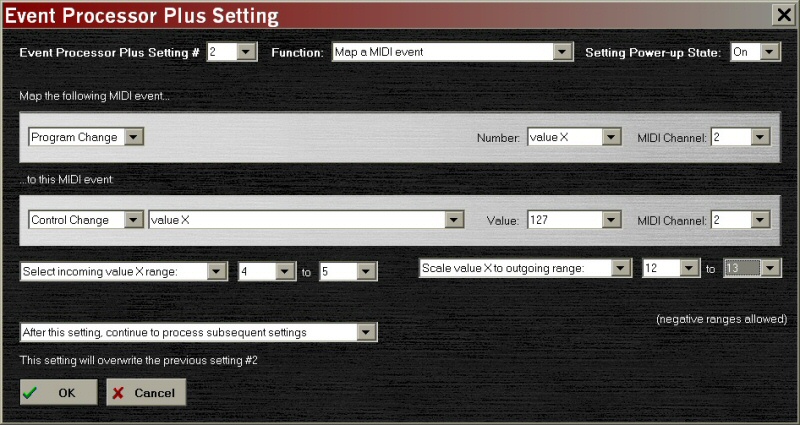
Figure 25 -– Using Program Changes to Turn CCs On
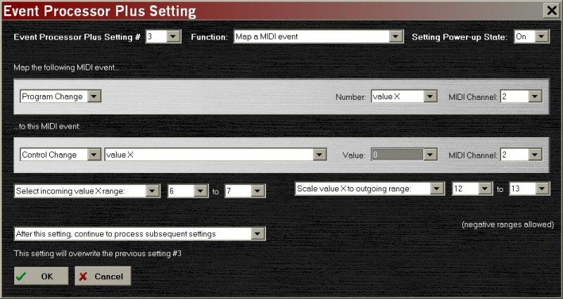
Figure 26 -– Turning the CCs Off
Because of the number of banks in the foot controller, we will need four variations of each of these two Settings to support the full configuration of the foot controller, thus making this example suitable only to the Event Processor Plus. Why so many –- can’t Banks 1, 3, 5, and 7 be combined, and then mapped as CC messages? Unfortunately, no: while the outside world sees only the final results of the Event Processor, inside the device the 32 individual Program Change messages are still intact.
SUPER-CONTROLLER #2
OK, we’re happy with our pedal controller, except for the on-on-off-off order of the effects controls. What if we want to arrange CC#12 and CC#13 in the more common on-off order? It’s easier to leave a foot in between two switches, and learn to nudge left or right to turn a particular control on or off, than to make the larger jump over an unwanted switch. Is there a way to work around this seeming limitation, and put each controller’s switches next to each other?
Figure 27 and 28 show another way to solve this problem, which results in a very compact solution that is not as intuitive to program, but very intuitive to use. Instead of breaking our problem down into ‘on’ events and ‘off’ events, let’s work on each CC function separately, and use reverse scaling to call up on and off values. The lower Program Change of each Setting calls the ‘on’ value, while the higher Program Change calls the ‘off’ value. Since there are only two values to the scaling, we could safely call any two numbers, rather than just on and off; our reverb switch pair could just as easily call up values of 127 for "lots of reverb" and 25 for "a little reverb."

Figure 27 -– Controlling CC#12 Directly
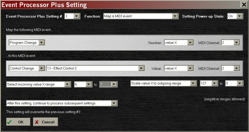
Figure 28 -– Controlling CC#13 Directly
This illustrates a useful point to remember: There are often several ways to solve a problem in the Event Processor, and some of the ways may be more efficient in the long run, if the mapped items can be grouped properly. Sometimes it’s possible to do more than 10 tasks in an Event Processor, or more than 32 tasks in an Event Processor Plus. In this case, a single Setting is both changing the switch function and scaling the values.
VELOCITY SENSITIVITY FROM AN ORGAN
For our final Variable-based example, let’s consider using a MIDI organ to control a piano module. While many modern MIDI organs can send velocity information, let’s say that we want to use a vintage organ with a MIDI retrofit, and these retrofits normally send fixed velocity. This is a very poor combination, because a piano’s real strength is in the timbre changes brought on by changes in volume. We can use a volume pedal to change the output volume of the piano module, but it won’t have anywhere near the expressiveness of a real piano. Unfortunately, the organ’s MIDI retrofit doesn’t send any CC that would help us out.
However, we could keep track of the organ’s volume pedal, and use that information to change the velocity data that the keyboard sends. It’s not a perfect answer, but most organists are used to using the expression pedal to provide tonal changes, so it just might work! Figure 29 and 30 describe how this process works. Setting #7 saves off the value of any expression pedal messages that come from the organ, and Setting #8 substitutes that value for the velocity data in the Note On messages.
Please note that we are only acting on the velocity range 1 – 127 because a Note On with velocity of zero is considered a Note Off.
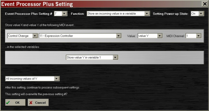
Figure 29 -– Saving the Expression Data
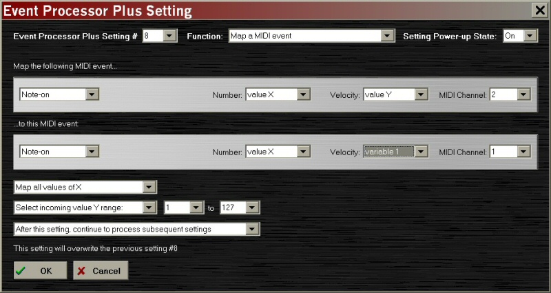
Figure 30 -– Sending Expression as Velocity
DELAYS AND OTHER ‘HARMLESS’ MIDI STRINGS
Sometimes it’s necessary to delay between sending MIDI messages, or to pad an uneven cycle of Settings to meet the requirements of the Cycle function. One of the most common places where this limitation rears its ugly head is during Program Changes: some MIDI devices effectively go off-line for as much as a second when changing stored sounds! (Those of you who own some of these products are probably more than aware of the performance implications.) MIDI, unfortunately, has no ‘hold’ or ‘wait’ command, and it’s not possible to pause the Event Processor to wait for a better time to send a message. One way to get around this restriction is to send some extra MIDI data after a required message, using up the MIDI data line for a period of time.
One of the most harmless things that I can think of to send is a ‘null SysEx’ message. SysEx messages are a special case of MIDI. They always start with F0 and end with F7; in between those two bytes, pretty much anything goes, although the strict convention is to send a device’s registered ID immediately after the F0, so all of the devices on the line can choose to obey or ignore the SysEx message. Each manufacturer who joins the MIDI Manufacturers Association is assigned a SysEx ID to use to route their own special messages to their devices.
There’s a bit of a loophole here that we can exploit. By sending only the F0 to start the message, then a 00 -– or a string of them -– and then terminating the message, nobody recognizes the SysEx message as "theirs," and everything goes on as before! In the meantime, though, the MIDI connection has been tied up with the SysEx message, preventing further communications. We’ve tricked MIDI into generating a pause! Figure 31 shows an event that triggers a 25-byte null SysEx message, resulting in 8.3 milliseconds of delay.
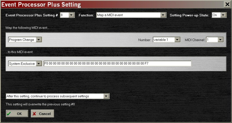
Figure 31 -– Null SysEx Transmission
What’s wrong with this method? Nothing really, even though MIDI devices don’t plan for pauses. A SysEx message has a high priority, and most other MIDI communications must stop and let the SysEx go through. For brief pauses between songs, it works well. The Event Processor allows SysEx strings of up to 32 bytes, including the F0 and F7. Several SysEx events can be queued up back-to-back to create longer pauses. MIDI sends about 3,000 bytes of data per second, so figure that every three SysEx bytes equal 1 millisecond of pause, or 10 milliseconds per 32-byte SysEx event.
What else can we use, if SysEx doesn’t look like a good option? Here’s my personal favorite list, in order of decreasing harmlessness:
- MIDI CC IDs between CC#102 and CC#119 – hardly ever used, especially the ones over 110. I’ve used CC#116-CC#119 all the time for Event Processor features, with great success.
- Unused NRPN locations – there are a lot of these, but you’ll have to experiment to make sure that the chosen values are really unused. The nice thing is, with 16,000 choices, you’re bound to find one that nobody else claimed. Once you’ve found a harmless NRPN and laid claim to it, multiple Data Slider (CC#6) messages can be used to create long pauses –- unless your old-school keyboard already uses the Data Slider, outside of NRPN.
- MIDI CC IDs between CC#33 and CC#50 – be careful here, these commands sometimes access lesser used functions like synthesizer envelopes and such. If they’re free in your setup, though, sending them is completely harmless.
THE SELECTIVE SWITCH
There are times when it's necessary to break a connection between two MIDI devices. That thick, swirling combination of a dark synthesizer pad and classic rock organ sounds great during the verses, but it's way too muddy for the solo. Or maybe you've been "borrowing" your bandmate's harpsichord sound for a song break, but now it's time to go back to playing the piano sounds that your keyboard came with. Changing the transmit channel on the keyboard is one way to disconnect the MIDI path, but changing channels is sometimes hard to do on a keyboard with few dedicated knobs and switches.
Over the years, manufacturers have offered 'MIDI footswitches' to disconnect the cable between two MIDI keyboards or modules. These devices look and act like the A-B footswitches guitarists use to swap between two amplifiers, or between two channels of the same amp. Looks can be deceiving, though. Anyone who has used these devices knows that they have a dark side: The connection and disconnection is easy between songs, but harder to coordinate while playing. Disconnect the cable early, and sooner or later you're bound to find stuck notes, or bent pitches that no longer want to un-bend.
The Event Processor can create the same kind of switch, but only disconnect the MIDI messages you choose. That way, notes can end, volume can change, and bends can unbend, even after the channel has been disconnected. Figures 32 - 34 show how to use the Pitch Wheel as a 'valve' to connect and disconnect a second MIDI device. Settings #1 and #2 create the valve effect, while Setting #3 filters some, but not all of the note information going to Channel 8. The really slick part of this example is that the Pitch Wheel is still available for pitch bends, as long as they don't go all the way to either end of the control!
Notice that Setting #3 filters Note On events with velocity values from 1 to 127 only. Why should we keep zero velocity passing through? MIDI Note On events with zero velocity are treated as if they were Note Offs. In live performance, Note Offs are often far more important than Note Ons. This way, even if your right hand is still on a few keys when Channel 8 is disconnected, the notes will turn off when you remove your hands, regardless of whether your keyboards sends Note Offs or Note Ons with velocity = 0. We also allow Pitch Bend, and controllers like Sustain and Volume to pass though, so they will also remain active.
Note also that Setting #3 starts out in the On state, blocking Channel 8 notes. This requires a first push to the upper end of the Pitch Wheel to connect the keyboard to its slave device. We could have easily programmed it the other way. We can switch additional items like controllers, Program Change messages, or Note-Off commands in the same way. Just remember that it takes three Settings per item or range of items switched, because each Setting can only enable or disable one other Setting.
[This example is based on a real-world requirement for an Event Processor Plus. I'd like to thank my friend Eric for his novel idea for controlling the switch.]
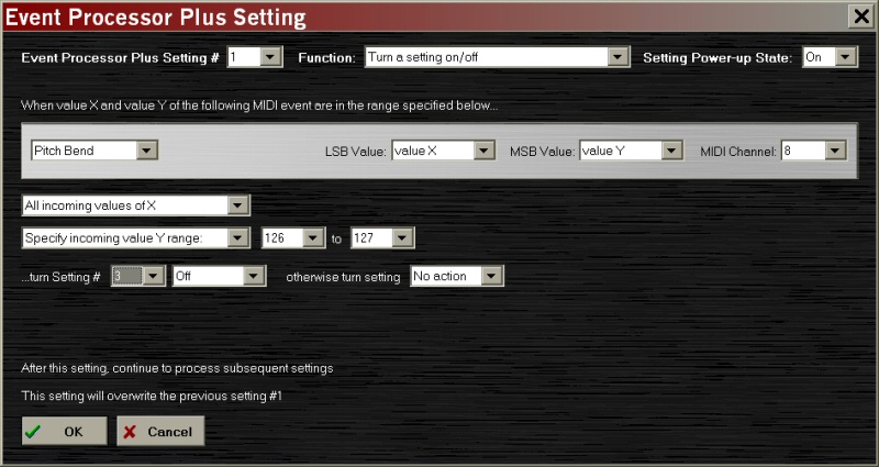
Figure 32 -- Using the Pitch Wheel to Control Channel 8, part 1
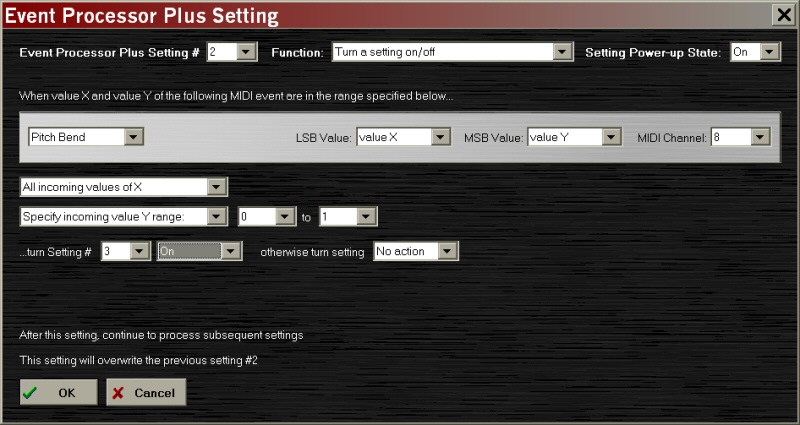
Figure 33 -- Using the Pitch Wheel to Control Channel 8, part 2
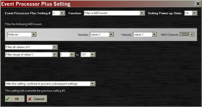
Figure 34 -- Selective Filtering of Channel 8
Previous Chapter
Next Chapter
Copyright © 2024 by Ashby Solutions. Used with permission by MIDI Solutions, Inc. This document may be freely copied and distributed in whole; sections of the document may not be used for other purposes without expressed written permission from Ashby Solutions. MIDI Solutions, the Event Processor, and the Event Processor Plus are trademarks of MIDI Solutions, Inc. of Vancouver, BC, Canada. Ashby Solutions and the Ashby Solutions logo are trademarks of Ashby Solutions of Ashby, MA, USA. All rights reserved.
Products | FAQs | Support | About | Order

Copyright © 2024 MIDI Solutions Inc.